Add to Cart
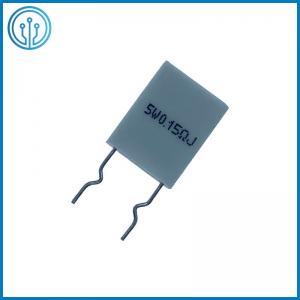
Vertical Mount Non-Inductance BPR Power Ceramic Housed Fixed Cement Resistor 5W 0.15R 5% Dip
Description Of The Ceramic Housed Fixed Cement Resistor 5W 0.15R 5% Dip
Ampfort’s wire wound resistors are made by winding the resistance wire around the glass fiber core or ceramic core. For high ohmage value and resistance range 1% the metal oxide film will be used instead of the wire wound. Two types of packaging are available. Type one using non-corrosive. Heat proof, humidity proof, and nonflammable.
Dimension Of The Ceramic Housed Fixed Cement Resistor 5W 0.15R 5% Dip (mm)

|
Type |
L±1.0 |
H±1.0
|
P±1.0 |
T±1.0 |
W±1.0 |
d±0.05 |
|
BPR 5W |
14 |
4-14 |
10 |
5 |
18 |
0.75 |
Power Derationg Curve & Temp.Rise Curve Of The Ceramic Housed Fixed Cement Resistor 5W 0.15R 5% Dip

Performance Specifications Of The Ceramic Housed Fixed Cement Resistor 5W 0.15R 5% Dip
|
Characteristics |
Standard |
Test Methods | |||
| 1. Temperature Coefficient of Resistors (PPM/℃) |
Wire Wound –80~+900
| Natural resistance change per temperature degree centigrade. (PPM/℃) R1: Resistance value at reference temp. (T1) R2: Resistance value at reference temp. (T2) T1: Room temperature T2 : T1+100℃ | |||
| 2. Dielectric Withstanding Voltage |
No evidence of flashover, mechanical damage or arcing or insulation break down |
Resistors shall be subjected to an approximately sinusoidal test potential (as below) 60Hz applied between both terminals connected together and a 90° V-Block extending beyond the end of the resistor | |||
| Resistor Wattage | AC or RMS Volts | ||||
| 1W ABOVE | 500 | ||||
| 3. Solderability |
90% Covered min. | The terminal lead shall be dipped into molten solder s at 3.2 to 4.8mm from the body of resistor. The temp. and time as below: a. 235±5℃ for 2±0.5 seconds b. 270±10℃ for 2±0.5 seconds | |||
| 4. Resistance to Soldering |
No evidence of mechanical damage ∆R / R at ±2% Max |
The terminal of the resistor is dipped into the molten solder of 350 ± 10℃for 3 ± 0.5 seconds. Then put the resistor in the room temperature. For 3 min. hours. | |||
| 5. Humidity Load Life |
±5% Max / 1000Hours |
Resistance change after 1000 hours (1.5 hours on 0.5 hours off) at rated continuous working voltage in a humidity chamber controlled at 40 ± 2℃and 90~95% relative humidity . | |||
| 6. Load Life |
±5% Max / 1000Hours | Permanent resistance change after 1000 hours operating at rated continuous working voltage with a duty cycle of 1.5 hours on 0.5 hours off at 70 ± 2℃ambient | |||
| 7. Temperature Cycling |
±2% Max with no evidence of mechanical damage |
Resistance change after continuous 5 cycles for duty cycle as specified below. | |||
| Step | Temperature | Time | |||
| 1 | -30℃ | 30 Minutes | |||
| 2 | +25℃ | 10~15 Minutes | |||
| 3 | +85℃ | 30 Minutes | |||
| 4 | +25℃ | 10~15 Minutes | |||
|
Characteristics |
Standard |
Test Methods |
| 8. Short Time Overload |
∆R / R at±3% Max with no evidence of arcing burning, or charring | Permanent resistance change after the application of a potential of 2.5 times rated continuous working voltage for 5 seconds at room temperature. |
| 9. Terminal Strength |
No evidence of mechanical damage or loosening terminals | Direct load resistance to 2.5kg direct load 30± 5 seconds twist test, for axial leads unit only. Terminal lead shall be bent through at a right angle at a point of 6.35mm from the body of resistor and shall be rotated through at a right angle about the original axis of the bent terminal in alternating direction for a total of 3 rotations. |
| 10. Burn Out |
The arcing and or flaming duration is less than 2seconds and the flame height is less than 1/2 inch. |
Resistors burning out or opening up for overloads in excess of 10 times rated wattage (regardless of how it is applied) |
Resistor Family Of The Ceramic Housed Fixed Cement Resistor 5W 0.15R 5% Dip


