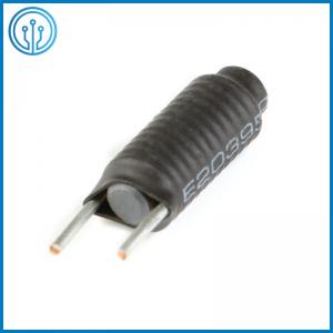
Copper Wire Winding Choke Coil Ferrite R5x20 Magnetic Rod Power Inductor 6uH P4mm
Description Of The R5x20 Magnetic Rod Power Inductor 6uH P4mm
Rod type (R type) choke, with current, firm structure, strong filtering ability characteristics, widely used in switching power supply and other electronic equipment.

Features Of The R5x20 Magnetic Rod Power Inductor 6uH P4mm
* Low-cost design
* Low-DC resistance and high-saturation current
* Less power loss and minimum thermal effect to peripheral components
* Low-radiation noise based on its toroidal construction
* Various material can meets with wide range of frequency requirement
* High-saturation material, wide inductance range
* Lead-free products
* Compliant with RoHS Directive
* Widely use in switching regulators and automotive systems, power amplifiers, power suppliers, SCR controls networks, EM and RFI suppression
Application Of The R5x20 Magnetic Rod Power Inductor 6uH P4mm
1. Switching power output and smoothing circuits
2. Used as choke coil for high frequency SMPs
3. Countermeasure against spike ripples
4. EMI/RFI filters
5. DC/DC converters
6. IP and OP devices
7. the buck converter
8. LCD
9. Notebook computer
10. Handheld notebook
11. Digital products,
12. Network communication
Dimensions Of The R5x20 Magnetic Rod Power Inductor 6uH P4mm(mm)
| Magnetic Rod | R5*20 |
| A | 10MAX |
| B | 22MAX |
| C | 5±0.2 |
| D | 6±2MM |
| F | 7mm ±1mm |
| E | 0.8±0.05mm |
| Winding | 0.8mm (2UEW) 16.5TS, CLOCKWISE, temperature resistance 155 degrees.
Actual measurement 5.9 UH Test condition: 1KHz 0.25V |
Technical Requirements Of The R5x20 Magnetic Rod Power Inductor 6uH P4mm
1) The appearance should not have any defects such as cracking, deformation, sticking tin beads, etc.;
2) The thread direction is counterclockwise, tightly wound;
3) PIN cannot be electroplated, and there must be no obvious tin tip or oxidation on the PIN;
4) The wire must not have obvious color difference;
5) The solder range is the outer edge of the flat coil
6) Products meet environmental protection requirements
Series Electrical properties Of The R5x20 Magnetic Rod Power Inductor 6uH P4mm
| Type | Amax | Bmin | Crel | Dmax | E±0.05 | Fmax |
| R0205 | 6 | 5 | 5 | 3.5 | 0.2-2.0mm | 1.5 |
| R0310 | 11 | 5 | 8 | 5 | 0.2-2.0mm | 1.5 |
| R0415 | 16 | 5 | 12 | 5.5 | 0.2-2.0mm | 1.5 |
| R0520 | 21 | 5 | 18 | 7 | 0.2-2.0mm | 1.5 |
| R0630 | 31 | 5 | 28 | 9.5 | 0.2-2.0mm | 1.5 |
| R0820 | 23 | 5 | 18 | 16 | 0.2-2.0mm | 1.5 |
| R1040 | 42 | 5 | 38 | 24 | 0.2-2.0mm | 1.5 |
Series Detailed parameters Of The R5x20 Magnetic Rod Power Inductor 6uH P4mm
| Part No | Inductance
(uH) | DCR
(OHM )
MAX | Rated
Current
(AMP)
MAX | SRF
(MHz) MIN | Wire
Diameter
(mm) | Ts | Weight
(g/pcs) |
| R0205-1R0K | 1 | 0.04 | 0.56 | 200 | 0.3 | 11.5 | 0.15 |
| R0205-1R2K | 1.2 | 0.04 | 0.56 | 180 | 0.3 | 12.5 | 0.165 |
| R0310-1R8K | 1.8 | 0.026 | 1.9 | 160 | 0.55 | 11.5 | 0.7 |
| R0310-2R2K | 2.2 | 0.028 | 1.57 | 150 | 0.5 | 13.5 | 0.714 |
| R0310-2R7K | 2.7 | 0.03 | 1.57 | 140 | 0.5 | 15.5 | 0.729 |
| R0310-3R3K | 3.3 | 0.035 | 1.27 | 135 | 0.45 | 17.5 | 0.686 |
| R0310-3R9K | 3.9 | 0.05 | 1 | 110 | 0.4 | 18.5 | 0.634 |
| R0310-4R7K | 4.7 | 0.07 | 0.76 | 90 | 0.35 | 19.5 | 0.575 |
| R0415-4R7K | 4.7 | 0.024 | 2.26 | 90 | 0.6 | 17.5 | 1.6 |
| R0415-5R6K | 5.6 | 0.03 | 1.9 | 80 | 0.55 | 18.5 | 1.4 |
| R0415-6R8K | 6.8 | 0.04 | 1.57 | 80 | 0.5 | 18.5 | 1.4 |
| R0415-8R2K | 8.2 | 0.06 | 1.27 | 80 | 0.45 | 21.5 | 1.32 |
| R0415-100K | 10 | 0.08 | 1 | 70 | 0.4 | 24.5 | 1.2 |
| R0520-100K | 10 | 0.04 | 2.65 | 60 | 0.65 | 22.5 | 3.1 |
| R0520-120K | 12 | 0.044 | 2.26 | 55 | 0.6 | 23.5 | 2.98 |
| R0520-150K | 15 | 0.06 | 1.9 | 45 | 0.55 | 27.5 | 2.97 |
| R0520-180K | 18 | 0.08 | 1.57 | 40 | 0.5 | 29.5 | 2.87 |
| R0520-220K | 22 | 0.1 | 1.27 | 38 | 0.45 | 32.5 | 2.73 |
| R0520-270K | 27 | 0.15 | 1 | 36 | 0.4 | 36.5 | 2.63 |
| R0630-4R7K | 4.7 | 0.005 | 16.08 | 85 | 1.6 | 12.5 | 10.2 |
| R0630-5R6K | 5.6 | 0.005 | 16.08 | 80 | 1.6 | 14.5 | 11 |
| R0630-6R8K | 6.8 | 0.008 | 10.61 | 75 | 1.3 | 15.5 | 8.68 |
| R0630-8R2K | 8.2 | 0.009 | 9.04 | 67 | 1.2 | 16.5 | 8.35 |
| R0630-100K | 10 | 0.01 | 9.04 | 64 | 1.2 | 19.5 | 8.8 |
| R0630-120K | 12 | 0.018 | 6.28 | 57 | 1 | 20.5 | 7.43 |
| R0630-150K | 15 | 0.023 | 5.08 | 53 | 0.9 | 23.5 | 7.23 |
| R0630-180K | 18 | 0.03 | 4.02 | 49 | 0.8 | 24.5 | 6.7 |
| R0630-220K | 22 | 0.045 | 3.07 | 44 | 0.7 | 27.5 | 6.24 |
| R0630-270K | 27 | 0.05 | 3.07 | 42 | 0.7 | 31.5 | 6.4 |
| R0630-330K | 33 | 0.06 | 2.65 | 36 | 0.65 | 35.5 | 6.53 |
| R0630-390K | 39 | 0.08 | 2.26 | 34 | 0.6 | 40.5 | 6.23 |
| R0630-470K | 47 | 0.11 | 1.9 | 32 | 0.55 | 44.5 | 6.22 |
| R0630-560K | 56 | 0.14 | 1.57 | 30 | 0.5 | 46.5 | 5.8 |
Characteristics of Ferrite Core Inductors
* In ferrite core inductors, the current passes to generate a magnetic field and the change in magnetic field results in the passing of an opposing current.
* They change electrical energy into magnetic energy and store the energy in them.
* They allow DC (Direct Current) but not AC (Alternating Current) to pass through them at higher frequencies.
* High Quality Factor - Material with low core losses; gapped ferrite core structure
* Performance over temperature - Closely controlled µi (initial permeability) versus temperature
* Minimum Stray Field - Use of toroid or pot core
* High inductance - Attained by using ferrite materials with high permeability